DNP3 Driver (Legacy)
The DNP3 Driver (Legacy) uses the DNP3 protocol for explicit reads and unsolicited messaging to acquire data. This driver is no longer actively supported with updates or fixes. For the latest option, see DNP3 Driver.
The DNP3 Driver (Legacy) does not support DNP3 Secure Authentication.
Data Acquisition
The DNP3 Driver (Legacy) driver supports two modes of acquiring data.
-
Explicit reads: Uses the DNP3 Read function code to retrieve static (current) values. Events are not processed in this mode. Recommended when points are addressed with group/variation/index (GVI) syntax.
-
Unsolicited messaging: Supports event-driven updates reported directly from the outstation. The driver processes these updates as they arrive. Sampling interval behavior for OPC UA clients still applies. Not all devices support unsolicited messaging.
Connecting to a Device
This driver requires the OPC UA module to be installed and enabled. If the module is missing or disabled, the device will fault with a “Missing Dependency” error on the Platform System > Modules page.
Ignition's DNP3 Driver (Legacy) can connect directly to any devices that support Ethernet communication through the master station. It is important to make a new device connection for each of the outstations (remote devices), setting the source and destination addresses for each in Ignition's device connection.
-
On the Gateway, go to Connections > Devices > Connections.

-
Click Create Device Connection +.
-
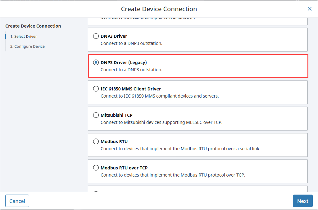
Select DNP3 Driver (Legacy) from the list and click Next.
-
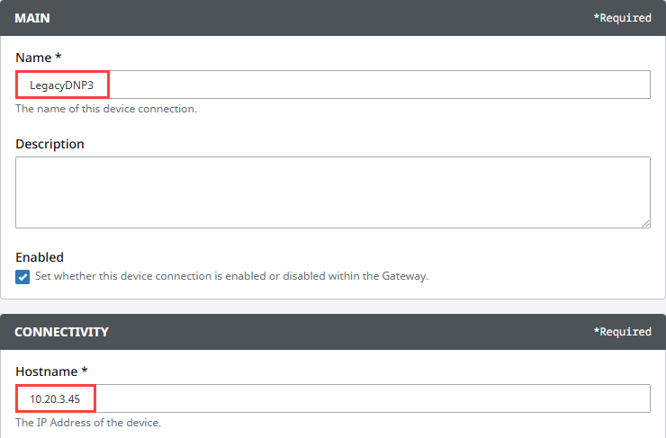
On the Configure Device screen, enter the required fields:
- Name: The desired name for the device (e.g., LegacyDNP3)
- Hostname: The IP address of the PLC (e.g., 10.20.4.55)
-
Click Create Device Connection.
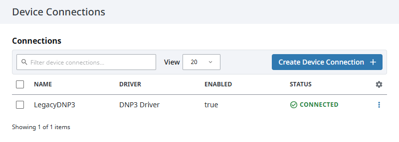
The device will be listed now on the Connections page. The status will initially show Disconnected, but will move to a Connected state.
Device Connection Settings
Main
| Name | Description |
|---|---|
| Name | A user-defined name for the device. This name appears in OPC item paths and the Devices list. Name must begin with an underscore or a letter, and cannot include special characters. |
| Description | Optional description to help identify the device. |
| Enabled | When selected, the device is active and available for use. |
Connectivity
| Property | Description |
|---|---|
| Hostname | The IP Address of the device. |
| Port | The port to use when connecting to a DNP3 device. The default port is 20000. |
| Local Address | The local address to connect from when establishing a TCP connection. If left blank, then the driver will simply pick an available address. |
| Source Address | Master station data link address, default 3. |
| Destination Address | Outstation data link address. Should be opposite of the source on the outstation. (e.g., Source Address is 3 and Destination Address is 4 or Source Address is 4 and Destination Address is 3) |
Advanced
| Property | Description |
|---|---|
| Message Fragment Size | The maximum size of a message fragment in the application layer, default is 249. |
| Message Timeout | The amount of time to wait for a message response from the outstation, default is 5,000. |
| Retries | The number of retries on a message timeout, default is 0. |
| Time Synchronization Enabled | When true, automatically synchronizes the gateway time to the outstation when requested, default is true. |
| Default Outstation Conformance Level | The default DNP3 Application Layer level subset to use when communicating with the outstation. |
| Direct Operate Enabled | When true, the Direct-Operate function code is used on a write, otherwise Select-Operate is used, default is true. |
| Unsolicited Messages Enabled | When true, the outstation may send unsolicited messages for Class 1, 2, and 3 data, default is false. Ignition will connect to the outstation, but not request any data from it. Ignition waits for the outstation to send data. Not all devices support this option; those that do need to be configured to use it. Please refer to your device's documentation for more information. |
| Integrity Poll Interval | The interval at which to perform an integrity poll, in milliseconds, default is 3,600,000. |
Default Value Types
| Property | Description |
|---|---|
| Analog Input Points | The default value type to use when reading an analog input point. Default is INTEGER. |
| Analog Input Frozen Points | The default value type to use when reading a frozen analog input point. Default is INTEGER. |
| Analog Output Points | The default value type to use when reading/writing an analog output point. Default is INTEGER. |
| Counter Points | The default value type to use when reading a counter point. Default is INTEGER. |
| Counter Frozen Points | The default value type to use when reading a frozen counter point. Default is INTEGER. |
| Binary Input Points | The default value type to use when reading a binary input point. Default is WITH_FLAGS. |
| Double-Bit Binary Input Points | The default value type to use when reading a double-bit binary input point. Default is WITH_FLAGS. |
| Binary Output Points | The default value type to use when reading a binary output point. default is WITH_FLAGS. |
Addressing and Browsing DNP3 Points
When the driver connects to an outstation, it performs an integrity poll to map available points to the OPC UA server with group, variation, and index addressing. You can review these mapped points in the Designer under the Connected Devices window.
Point Types
| Type Name | Group | Supported Variations |
|---|---|---|
| SingleBitBinaryInput | 1 | 1 - Packed format 2 - With flags |
| DoubleBitBinaryInput | 3 | 1 - Packed Format 2 - With flags |
| Binary Output | 10 | 1 - Packed Format 2 - With flags |
| Counter | 20 | 1 - 32-bit with flags 2 - 16-bit with flags 5 - 32-bit 6 - 16-bit |
| FrozenCounter | 21 | 1 - 32-bit with flags 2 - 16-bit with flags 5 - 32-bit with flags and time 6 - 16-bit with flags and time 8 - 32-bit 10 - 16-bit |
| AnalogInput | 30 | 1 - 32-bit with flags 2 - 16-bit with flags 3 - 32-bit 4 - 16-bit 5 - Float with flags 6 - Double with flags |
| FrozenAnalogInput | 31 | 1 - 32-bit with flags 2 - 16-bit with flags 3 - 32-bit with time of freeze 4 - 16-bit with time of freeze 5 - 32-bit 6 - 16-bit 7 - Float with flags 8 - Double with flags |
| AnalogOutput | 40 | 1 - 32-bit with flags 2 - 16-bit with flags 3 - Float with flags 4 - Double with flags |
| OctetString | 110 | 0 - 225 |
For variation details, consult your device’s documentation.
Aliased Points
Aliased points let you assign meaningful names and folder paths to DNP3 points. They are especially useful for addressing points that were not returned during the initial integrity poll.
The options within the Aliased Points panel are described in the table below:
| Button | Description |
|---|---|
| Import Configuration File | Allows users to import a CSV file to add many data points at once. |
| Reset | Resets the program to its default state before any changes were saved. |
| Export | Allows users to export the configuration file as a CSV. |
| Remove All | Removes all entries from the program. |
| Add + | Allows users to manually add individual data points. |
When adding individual aliased points or importing configuration files, it is helpful to know what fields Ignition is expecting. These fields are detailed by the table below:
| Property | Description |
|---|---|
| Point Address | The group, variation, and index that fully describe a point. A full address includes:
g30v1i20 |
| Browse Path | A / separated folder path where the point should appear.Example: Facility1/Voltage |
| Description | A user-defined description of the point. [Optional] |
If you change a point address after creating tags, you must update the OPC Item Path for those tags.
For a walkthrough of how to add an aliased point, see Browsing Points With Legacy DNP3 Example (Aliased Points).