Omron NJ Driver
Connect to an Omron NJ Device
This driver requires the OPC UA module to be installed and enabled. If the module is missing or disabled, the device will fault with a “Missing Dependency” error on the Platform > System > Modules page.
-
On the Gateway, go to Connections > Devices > Connections.

-
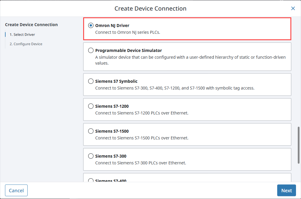
Click Create Device Connection +.
-
Select Omron NJ Driver and click Next.
-
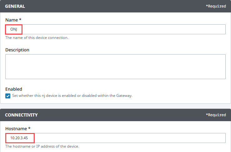
On the Configure Device screen, enter the required fields:
- Name: The desired name for the device (e.g., ONJ)
- Hostname: The IP address of the PLC (e.g., 10.20.3.45)
-
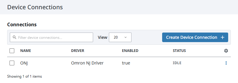
Click Create Device Connection.
The device will be listed now on the Connections page. The status will initially show Disconnected, but will move to a Connected state.
Device Settings
General
| Name | Description |
|---|---|
| Name | A user-defined name for the device. This name appears in OPC item paths and the Devices list. Name must begin with an underscore or a letter, and cannot include special characters. |
| Description | Optional description to help identify the device. |
| Enabled | When selected, the device is active and available for use. |
Main
| Name | Description |
|---|---|
| Hostname | Specifies the IP address of the device. |
| Local Address | Specifies the local address to connect from when establishing a TCP connection. If left blank, the driver will automatically select an available address. |
| Timeout | Sets the request timeout in milliseconds. The default value is 2,000. |
Advanced
| Name | Description |
|---|---|
| Connection Size | Specifies the CIP connection size to use. The default and maximum value is 1,994 bytes. |
| Date/Time Offset | Sets the offset, in hours, applied to date/time values when reading or writing. The default value is 0. |
| Slot Number | Specifies the slot number in the backplane where the CPU is located. The default value is 0. |
| Concurrency | Defines the number of concurrent requests the driver is allowed to issue. There is a 1:1 correlation between this value and the number of CIP connections used. The default is 2. |
Exporting from the Device
To export variables from Sysmac Studio, navigate to the global variables and select Tools > Export Global Variables > CX-Designer.
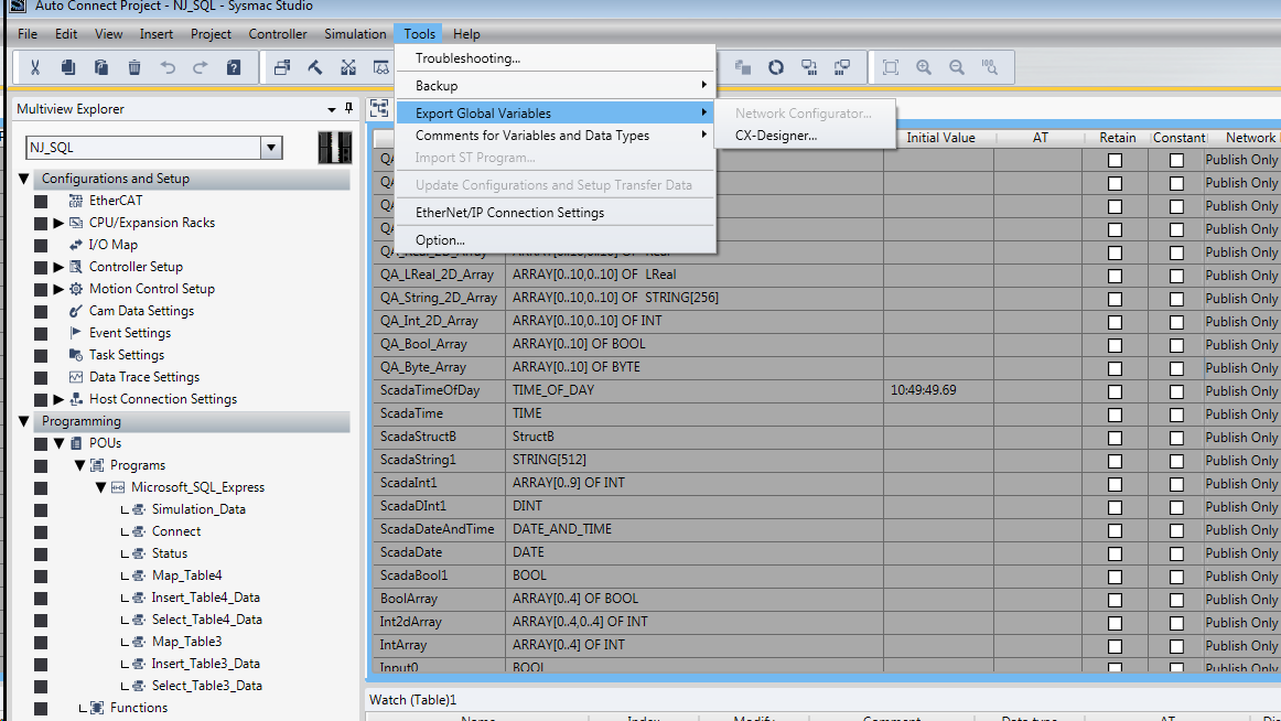
The variables will be saved to the clipboard in tab-separated format. You can now paste the contents into an empty text file for use with importing into the Ignition Gateway.
Managing Tags
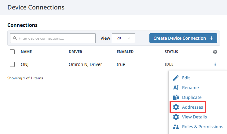
In order to browse tags in the Designer, you must first create a mapping for the device in the Gateway. You can access this by clicking the three dot menu and selecting Addresses.
Importing Tags
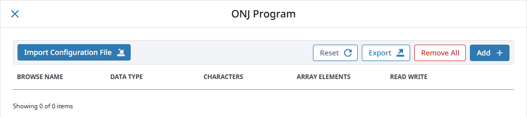
To manage tags, you can manually enter the tags, or import them from a tab-separated file. When importing, first click the Import Configuration File button, then choose a file to append tags to the table.
Once you save any changes made to the tag mapping, you can view the tags in the Connected Devices window of the Designer.
Addressing
In the table of tags, we have five columns of configuration per tag.
| Column | Description |
|---|---|
| Browse Name | The address of the variable in the Omron device. Struct members are separated with periods. |
| Datatype | The datatype of the variable as found in the Omron device. |
| Characters | The maximum number of characters allowed for a String tag. |
| Elements | Indicates whether the tag is a scalar or an array. Refer to the section on specifying element counts for more details. |
| R/W | Specifies read/write access permissions for the tag. |
Support for the following data types is included:
- TIME_NSEC
- DATE_NSEC
- TIME_OF_DAY_NSEC
- DATE_AND_TIME_NSEC
Scalars
Leaving the Elements column blank will result in a scalar tag. When reading from the device, only one element will be requested.
Arrays
Specify the number of elements in an array in the form of 0..N. The initial index 0 is always included, so an array mapped with 0..9 elements is a 10 element array.
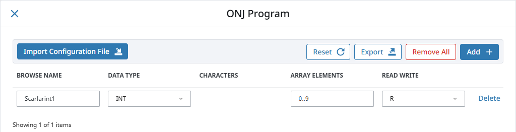
Array elements may also be specified with a single integer representing the last offset. For example, an integer value of 5 is equivalent to 0..5.
The number range specified in the Elements field can deviate from the range specified in the device's program. Thus, if an array was configured with a range of 0 - 4, but the mapping on the Ignition Gateway is set to 3 - 7, then the resulting items would be offset as follows:
| PLC Program | Tag in Ignition |
|---|---|
| 0 | BoolArray_3_ |
| 1 | BoolArray_4_ |
| 2 | BoolArray_5_ |
| 3 | BoolArray_6_ |
| 4 | BoolArray_7_ |
This is because the driver always assumes that the lowest configured element on the mapping page matches up with the lowest element in the PLC program. As seen above, this can cause some confusion if the mapping on the Ignition Gateway is configured with a different range.
For this reason, it is highly recommended to configure the Elements field on the Ignition Gateway to match the range used in the PLC program.
Note, that this also applies to Multidimensional Arrays.
Multidimensional Arrays
Multidimensional arrays are specified in the same way as arrays with each group of indices separated by a comma. For example, entering 0..3,0..3 into the Array Elements field specifies two groups of indices.
Strings
The number of characters for String variables is specified in the Chars field. String arrays are mapped using both the Chars and Elements fields.