Omron FINS Driver
Ignition supports Omron FINS devices. This driver supports both UDP and TCP transport protocols.
Connect to an Omron FINS Device via TCP
This driver requires the OPC UA module to be installed and enabled. If the module is missing or disabled, the device will fault with a “Missing Dependency” error on the Platform > System > Modules page.
-
On the Gateway, go to Connections > Devices > Connections.

-
Click Create Device Connection +.
-
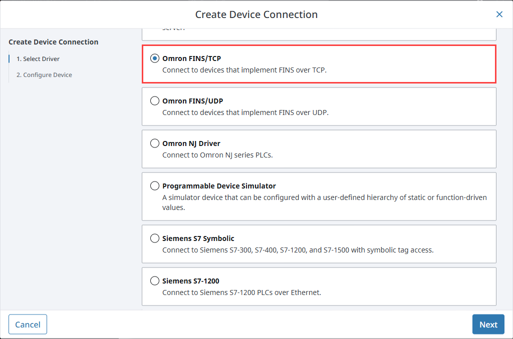
Select Omron FINS/TCP and click Next.
-
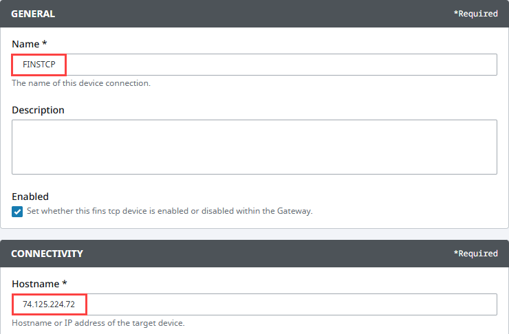
On the Configure Device screen, enter the required fields:
- Name: The desired name for the device (e.g., FINSTCP)
- Hostname: The IP address of the PLC (e.g., 74.125.224.72)
-
Click Create Device Connection.
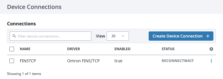
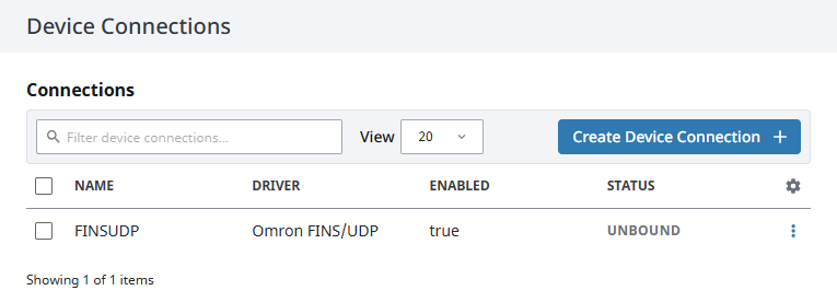
The device will be listed now on the Connections page. The status will initially show Disconnected, but will move to a Connected state.
Omron FINS/TCP Settings
General
| Name | Description |
|---|---|
| Name | A user-defined name for the device. This name appears in OPC item paths and the Devices list. Name must begin with an underscore or a letter, and cannot include special characters. |
| Description | Optional description to help identify the device. |
| Enabled | When selected, the device is active and available for use. |
Connectivity
| Name | Description |
|---|---|
| Hostname | The hostname or IP Address of the device. |
| Port | The port your Omron device is listening on. The default is 9600. |
| Local Address | Address of network adapter to connect from. |
| Timeout | The request timeout, specified in milliseconds. The default is 2,000. |
FINS Settings
| Name | Description | Valid Value |
|---|---|---|
| FINS Source Network | The address number of the source network (the Ignition Gateway). | Valid value is an integer between 0 and 127. The default setting is 0. |
| FINS Source Node | The number of the source node (the Ignition Gateway), typically the last octet of the IP address. | Valid value in an integer between 0 and 254. The default setting is 0. |
| FINS Source Unit | The unit number of the source device (the Ignition Gateway). | Valid value is an integer between 0 and 255. The default setting is 0. |
| FINS Destination Network | The address number of the destination network (the FINS device). | Valid value is an integer between 0 and 127. The default setting is 0. |
| FINS Destination Node | The number of the destination node (the FINS device), typically the last octet of the IP address and set via dials on the front of the device. | Valid value in an integer between 0 and 254. The default setting is 0. |
| FINS Destination Unit | The unit number of the destination device (the FINS device). | Valid value is an integer between 0 and 255. The default setting is 0. |
Request Optimization
| Name | Description |
|---|---|
| Concurrent Requests | The number of requests that Ignition will try to send to the device at the same time. Increasing this number can sometimes help with your request throughput, however increasing this too much can overwhelm the device and hurt communications with the device. |
| Max Request Size | The maximum size of a request in bytes. |
| Max Gap Size | The maximum address “gap” to span when optimizing requests to contiguous address locations. |
| Write Priority Ratio | The number of write requests to execute for every read request, when an abundance of both are queued for execution. |
Connect to an Omron FINS Device via UDP
-
On the Gateway, go to Connections > Devices > Connections.
-
Click Create Device Connection +.
-
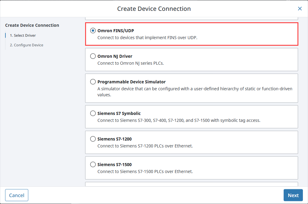
Select Omron FINS/UDP and click Next.
-
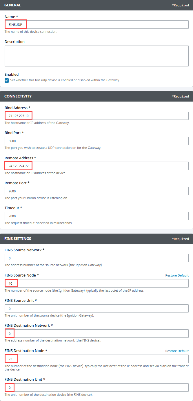
On the Configure Device screen, enter the required fields:
- Name: The desired name for the device (e.g., FINSUDP)
- Bind Address: The hostname or IP address of the Gateway (e.g., 74.125.224.10)
- Remote Address: The hostname or IP address of the device(e.g., 74.125.224.72)
- FINS Source Node: The number of the source node (the Ignition Gateway), typically the last octet of the IP address (e.g., 10)
- FINS Destination Node: The number of the destination node (the FINS device), typically the last octet of the IP address and set via dials on the front of the device (e.g., 72)
- FINS Destination Unit: The unit number of the destination device (the FINS device)
-
Click Create Device Connection.
The device will be listed now on the Connections page. The status will initially show Disconnected, but will move to a Connected state.
Omron FINS/UDP Settings
General
| Name | Description |
|---|---|
| Name | A user-defined name for the device. This name appears in OPC item paths and the Devices list. Name must begin with an underscore or a letter, and cannot include special characters. |
| Description | Optional description to help identify the device. |
| Enabled | When selected, the device is active and available for use. |
Connectivity
| Name | Description |
|---|---|
| Bind Address | The hostname or IP address of the Gateway |
| Bind Port | The port you wish to create a UDP connection on for the Gateway. The default is 9600. |
| Remote Address | The hostname or IP address of the device. |
| Remote Port | The port your Omron device is listening on. The default is 9600. |
| Timeout | The request timeout, specified in milliseconds. The default is 2,000. |
FINS Settings
| Name | Description | Valid Value |
|---|---|---|
| FINS Source Network | The address number of the source network (the Ignition Gateway). | Valid value is an integer between 0 and 127. The default setting is 0. |
| FINS Source Node | The number of the source node (the Ignition Gateway), typically the last octet of the IP address. | Valid value in an integer between 0 and 254. The default setting is 0. |
| FINS Source Unit | The unit number of the source device (the Ignition Gateway). | Valid value is an integer between 0 and 255. The default setting is 0. |
| FINS Destination Network | The address number of the destination network (the FINS device). | Valid value is an integer between 0 and 127. The default setting is 0. |
| FINS Destination Node | The number of the destination node (the FINS device), typically the last octet of the IP address and set via dials on the front of the device. | Valid value is an integer between 0 and 254. The default setting is 0. |
| FINS Destination Unit | The unit number of the destination device (the FINS device). | Valid value is an integer between 0 and 255. The default setting is 0. |
Request Optimization
| Name | Description |
|---|---|
| Concurrent Requests | The number of requests that Ignition will try to send to the device at the same time. Increasing this number can sometimes help with your request throughput, however increasing this too much can overwhelm the device and hurt communications with the device. |
| Max Request Size | The maximum size of a request in bytes. |
| Max Gap Size | The maximum address “gap” to span when optimizing requests to contiguous address locations. |
| Write Priority Ratio | The number of write requests to execute for every read request, when an abundance of both are queued for execution. |
Import Addresses
There is a user interface in the Gateway to create import addresses. After import, you'll be able to browse the tags in the Designer.
-
On the Gateway, go to Connections > Devices > Connections.
-
On the Device Connections page, click the three dots menu next to the Omron FINS device and select Addresses.
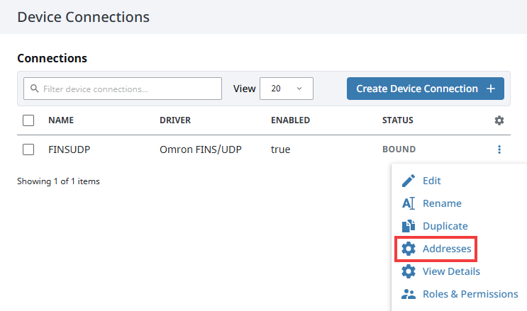
-
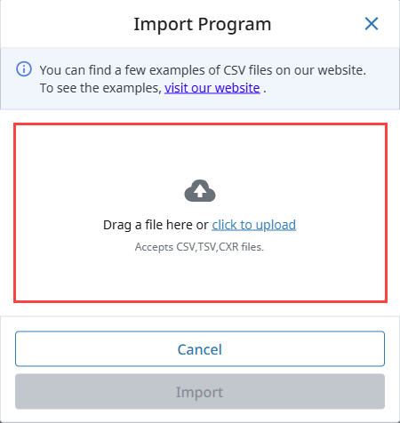
In the pop out panel, click the Import Configuration File button and upload the addresses from a CSV, TSV, or CXR file.
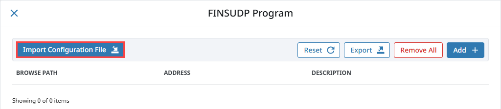
-
After uploading a configuration file, click Import.
-
The tags and their values will be displayed. Click Save Configuration.
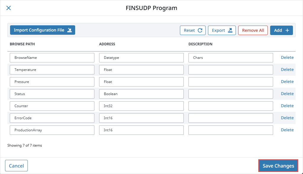
-
Once any changes are saved, you can view the tags in the Connected Devices window of the Designer.
Addressing
You also have the option to manually address tags via an Ignition OPC tag in the Ignition Designer. See Ignition OPC UA Server Node Configuration for more information.
Data Areas
| Area | Ignition Code | Omron Symbol Code | Native Size |
|---|---|---|---|
| CIO Area | CIO | Int16/UInt16 | |
| Work Area | WR or W | W | Int16/UInt16 |
| Holding Bit Area | HR or H | H | Int16/UInt16 |
| Auxiliary Bit Area | AR or A | A | Int16/UInt16 |
| Timer Area | TIM or T | T | Int16/UInt16 or Bool |
| Counter Area | CNT or C | C | Int16/UInt16 or Bool |
| Index Register Area | IR | IR | Int32/UInt32 |
| Data Register Area | DR | DR | Int16/UInt16 |
| DM area | DM or D | D | Int16/UInt16 |
| EM area | EM or Exx | E | Int16/UInt16 |
EM Area
Use EM for the current bank, or Exx for bank xx, where xx is 2 hex digits.
Valid banks are E00 through E18 (hex), totaling 25 banks.
Data Types
- Bit
- Bool
- Int16
- Int32
- Int64
- UInt16
- UInt32
- Float
- Double
- String
- BCD16
- BCD32
Data Type Modifiers
| Modifier | Order |
|---|---|
| @BE | Big Endian Byte Order (default when not specified) |
| @LE | Little Endian Byte Order |
| @HL | High-Low Word Order |
| @LH | Low-High Word Order (default when not specified) |
Examples
Syntax Example
Items in curly brackets {} are optional.
Below is an example OPC Item path, representing how to manually specify an address in the device.
ns=1;s=[DeviceName]Area{<DataType>}Offset{.Bit}
When typing Addresses in using the Device's Address page on the gateway, the syntax looks like the following:
Area{<DataType>}Offset{.Bit}
More Examples
| Item Path (OPC UA NodeId) | FINS Request |
|---|---|
| CIO0 | An Int16 at offset 0 in CIO area. |
| CIO<Int32>1 | An Int32 at offset 1 in CIO area. |
| CIO<Int64>3.0 | Bit 0 of an Int64 at offset 3 in CIO area. |
| CIO<Int64@HL>3 | An Int64 at offset 3 in CIO area in High-Low word order. |
| TIM0 | Present Value (16-bit) of Timer at offset 0. |
| TIM<Bool>0 | Completion Status (Bool) of Timer at offset 0. |
| CNT0 | Present Value (16-bit) of Counter at offset 0. |
| CNT<Bool>0 | Completion Status (Bool) of Counter at offset 0. |
| DR0 | An Int32 at offset 0 in DR area (32-bit by default). |
| DR<Int64>0 | An Int64 at offset in DR area. |
| CIO<Int16[3]>0 | An Int16 array of size 3 at offset 0 in CIO area. |
| CIO<Int16[3]>0[1] | Element 1 of an Int16 array of size 3 at offset 0 in CIO area. |
| CIO<String10>0 | String of up to length 10 (string length in bytes) at offset 0 in CIO area. |
| E001000 | An Int16 from EM bank 0 at offset 1000. |
| E00<Int16>1000 | Also an Int16 from EM bank 0 at offset 1000, but with the an explicit DataType to make the address look less confusing. |
| E001000 | An Int16 from EM bank 0 at offset 1000. |
| TIM0 | Present Value (16-bit) of Timer at offset 0. |
| TIM<Bool>0 | Completion Status (Bool) of Timer at offset 0. |
Ignition OPC UA Server Node Configuration
You can also create OPC Nodes in Ignition’s OPC UA server manually via a CSV file on the Ignition Gateway itself using the settings in the table below.
| Name | Value |
|---|---|
| File Name | tags.csv |
| File Location | $ignitionHome/data/opcua/devices/$deviceName |
| File Format | Comma-separated value file with the following columns:
|
Example File
Tag1, CIO0, "First tag"
Foo/Tag2, CIO1, "Second tag, in a folder"
Foo/Bar/Tag3, CIO2, "In a couple of folders"
Use quotes on the description when it contains a comma (or whenever you like).
When adding or making changes to this file, a restart of the device is necessary for the changes to be picked up. This is done by editing the device and clicking Save.