DNP3 Driver
The DNP3 Driver provides communication with DNP3 outstations over Ethernet, supporting event-based polling, unsolicited messaging, and explicit reads using the DNP3 protocol. For information about the older version, see DNP3 Driver (Legacy).
The DNP3 Driver does not support DNP3 Secure Authentication.
Data Acquisition
The DNP3 Driver supports three modes of acquiring data.
-
Event-based polling: The primary method, using configured polling intervals for Class 1, 2, and 3 events. Events that occur between polls are preserved and processed sequentially. OPC UA clients with a sampling interval of 0 will receive all events in order.
-
Unsolicited messaging: Available on supported outstations, where the device pushes events as they occur. The driver processes these as they arrive. Sampling interval behavior for OPC UA clients applies similarly to event-based polling.
-
Explicit reads: Used with group/variation/index (GVI) addressing, where static values are explicitly requested at each poll. No events are processed in this mode. This can approximate Legacy driver behavior if GVI tags are configured.
Connecting to a Device
This driver requires the OPC UA module to be installed and enabled. If the module is missing or disabled, the device will fault with a “Missing Dependency” error on the Platform System > Modules page.
Ignition's DNP3 driver can connect directly to any devices that support Ethernet communication through the master station. It is important to make a new device connection for each of the outstations (remote devices), setting the source and destination addresses for each in Ignition's device connection.
-
On the Gateway, go to Connections > Devices > Connections.

-
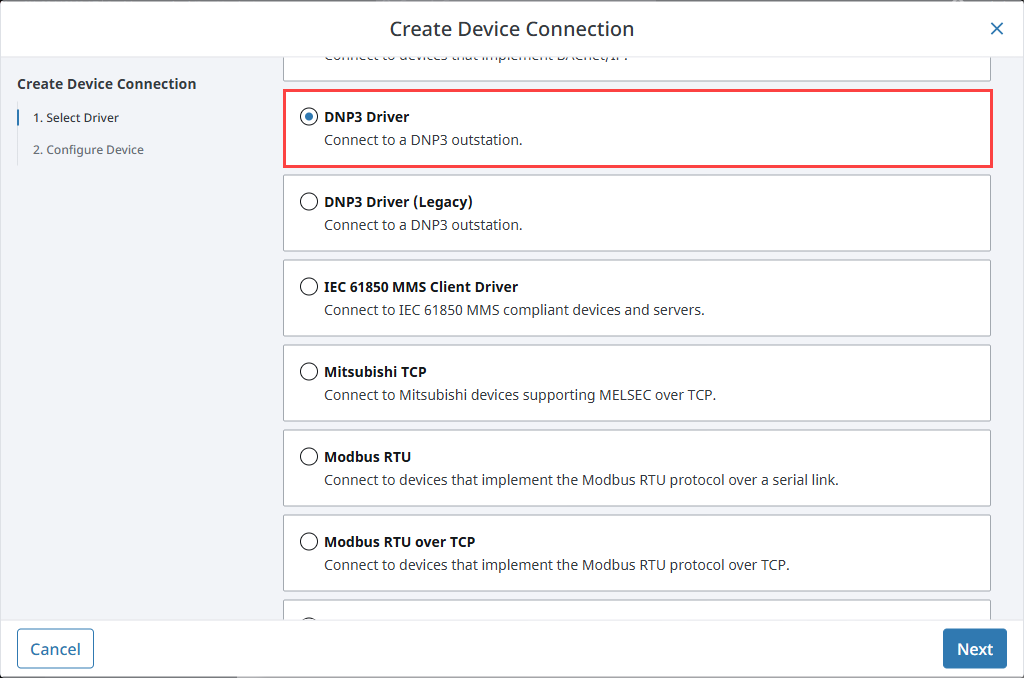
Click Create Device Connection +.
-
Select DNP3 Driver from the list and click Next.
-
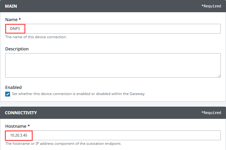
On the Configure Device screen, enter the required fields:
- Name: The desired name for the device (e.g., DNP3)
- Hostname: The IP address of the PLC (e.g., 10.20.4.55)
-
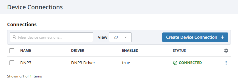
Click Create Device Connection.
The device will be listed now on the Connections page. The status will initially show Disconnected, but will move to a Connected state.
Connection Settings
Main
| Name | Description |
|---|---|
| Name | A user-defined name for the device. This name appears in OPC item paths and the Devices list. Name must begin with an underscore or a letter, and cannot include special characters. |
| Description | Optional description to help identify the device. |
| Enabled | When selected, the device is active and available for use. |
Connectivity
| Property | Description |
|---|---|
| Hostname | The hostname or IP address of the outstation device. |
| Port | The port component of the outstation endpoint. Default is 20000. |
| Source Address | The DNP3 data link address of the local (master) device. Default is 3. |
| Destination Address | The DNP3 data link address of the remote (outstation) device. Default is 4. |
| Response Timeout (ms) | The time to wait for a response from the outstation, in milliseconds. Default is 5000. |
| Keep Alive Timeout (ms) | The maximum inactivity time, in milliseconds, before a link-layer keep-alive message is sent. Default is 3,600,000. |
Data Acquisition
| Property | Description |
|---|---|
| Integrity Poll Period (ms) | How often to perform an integrity poll (requesting Class 1/2/3/0 data). Disabled if set to 0. Default is 3,600,000. |
| Class 1 Poll Period (ms) | How often to poll Class 1 event data. Disabled if set to 0. Default is 10,000. |
| Class 2 Poll Period (ms) | How often to poll Class 2 event data. Disabled if set to 0. Default is 10,000. |
| Class 3 Poll Period (ms) | How often to poll Class 3 event data. Disabled if set to 0. Default is 10,000. |
| Unsolicited Event Classes | Specifies which event classes are enabled for unsolicited reporting. Leave blank if unsolicited messaging is not being used. Default is blank. |
Advanced Properties
Analog Operation
| Property | Description |
|---|---|
| Command Mode | The command mode to use when issuing commands for analog outputs; DIRECT_OPERATE or SELECT_BEFORE_OPERATE. Default is DIRECT_OPERATE. |
| Read After Operate | Whether an explicit read should be issued after operating analog outputs. Useful when an outstation does not support generating analog output events or assigning them to a class. Default is false. |
| Read After Operate Delay | Delay, in milliseconds, the read operation after operating to the Analog outputs. Default is 0. |
Binary Operation
| Property | Description |
|---|---|
| Command Mode | The command mode to use when issuing commands for binary outputs; DIRECT_OPERATE or SELECT_BEFORE_OPERATE. Default is DIRECT_OPERATE. |
| Read After Operate | Whether an explicit read should be issued after operating binary outputs. Useful when an outstation does not support generating binary output events or assigning them to a class. Default is false. |
| Read After Operate Delay | Delay, in milliseconds, the read operation after operating to the Binary outputs. Default is 0. |
| Trip Close Code | The trip close code to use when issuing commands for binary outputs; NUL, CLOSE, or TRIP. Default is NUL. |
| Op Type | The operation type to use when issuing commands for binary outputs; LATCH or PULSE. Default is LATCH. |
| Count | The count to use when issuing commands for binary outputs. Default is 1. |
| On Time (ms) | The on-time to use when issuing commands for binary outputs. Default is 0. |
| Off Time (ms) | f-time to use when issuing commands for binary outputs. Default is 0. |
Logging
| Property | Description |
|---|---|
| Auto Time Sync | Enable automatic time synchronization when an outstation signals that it needs a time update by setting the NEED_TIME indicator bit. Default is true. |
| Application Layer Debug Logging | Whether to enable debug logging for the DNP3 application layer. Default is false. |
| Physical Layer Debug Logging | Whether to enable debug logging for the DNP3 physical layer. Default is false. |
Addressing and Browsing DNP3 Points
You can browse returned points under the Tag Browser's Connected Devices window in the Designer.
Sequence of Events
You can preserve the sequence of events by tuning your Tag Group:
- OPC UA Queue Size: increase to handle the maximum number of anticipated events. This is typically much larger than the buffer in a physical outstation.
- OPC UA Sampling Interval: set to 0 to allow true event-based reporting. Nonzero sampling intervals may collapse multiple events into a single update.
Sequence of events is best used with devices that support high-frequency event reporting and maintain their own internal event buffers.