Connecting to SLC
Connect to a Device
- Go to the Configure section of the Gateway webpage.
- Scroll down and select OPC-UA Server > Devices.
- On the Devices page, find the blue arrow and click on Create new Device.
- On the Add Device Step 1: Choose Type page, select Allen-Bradley SLC, and click Next.
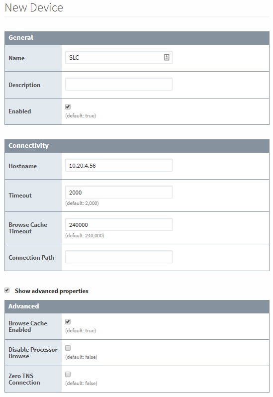
- On the New Device page, leave all the default values and type in the following fields:
- Name: SLC
- Hostname: type the IP address for the PLC
- Click Create New Device. The Devices page is displayed showing the SLC device is added to Ignition. The Status will show as Disconnected and then Connected.
- To see all the tags, navigate to the Configure section of the gateway, and click on Quick Client under OPC Connections. On the OPC Quick Client page, expand the folder matching the name used in step 5, and expand the Global folder to see available tags.
Device Connection Settings
The General settings are common to all Allen Bradley devices, and the Connectivity settings are device dependent.
General Settings
| Name | Description |
|---|---|
| Name | The user-defined name for this Device. The name chosen will show up in OPC Item Paths and under OPC-UA Server > Devices of the Configure page of the Gateway. The Device Name must be alphanumeric. |
| Description | The user-defined description for the device. This is only used as a note to differentiate between devices. |
| Enable Device | Only devices that are enabled appear in Connections > Devices of the Status page of the Gateway and thus have their tags available for use. |
Connectivity Settings
| Name | Description |
|---|---|
| Hostname | The Hostname value is the IP Address of the SLC processor. The protocol that the SLC processor supports is automatically detected. It will use either CSP protocol on port 2222 (0x8AE) or EthernetIP protocol on port 44818 (0xAF12). |
| Communication Timeout | After sending a request to the SLC processor, the Communication Timeout setting is the amount of time in milliseconds to wait for a response before treating it as a failure. |
| Browse Cache Timeout | When the data table layout is read from the SLC processor, the Browse Cache Timeout value is the amount of time in milliseconds to cache the results. |
| Connection Path | The Connection Path value is used to define the route of the SLC processor to connect to. Currently routing through the ControlLogix Ethernet Communication Interface Module (1756-ENET) to the ControlLogix Data Highway Plus-Remote I/O Communication Interface Module (1756-DHRIO) and on to a SLC processor of the DH+ network is supported. For a more in depth explanation of connection paths, see Allen Bradley Connection Paths Explained section. |
Advanced Settings
| Name | Description |
|---|---|
| Browse Cache Enabled | New in 7.9.13 Determines if browse results for the device should be cached. Default is enabled. |
| Disabled Processor Browse | If true, browsing the device is disabled. |
| Zero TNS Connection | If true, use a Transparent Network Substrate (request key) of zero for connection requests. |
More Information On Connection Path
The Connection Path format contains 4 numbers separated by commas. The first number is always 1 and tells the 1756-ENET module to route through the backplane. The second number is the slot number of the 1756-DHRIO module of the DH+ network the SLC processor is connected to. The third number is the channel of the 1756-DHRIO module that the SLC processor is connected to. Use 2 for channel A and 3 for channel B. The final and fourth number is the DH+ node number. This number is in octal and is the same as configured in the SLC processor. See the ControlLogix Ethernet Communication interface Module User Manual for more information.
Connection Path Format: 1,<1756-DHRIO slot number>,<1756-DHRIO channel>,<DH+ node number>
The valid range for the 1756-DHRIO slot number is between 0 and 16 but depends on the chassis size. The 1756-DHRIO channel is either 2 for channel A or 3 for channel B. The DH+ node number range is from 00 to 77 octal.
Supported SLC Connection Methods
- SLC505 direct
- SLC505, SLC504, SLC503 connected through 1761-NET-ENI
- SLC504 connected through 1756-DHRIO
- SLC505, SLC504, SLC503 connected through Spectrum Controls WebPort 500