Omron
Connecting Ignition to an Omron Device
- Go to the Configure section of the Gateway webpage.
- Scroll down and select OPC-UA Server > Devices.
- On the Devices page, find the blue arrow and click on Create new Device.
- On the Add Device Step 1: Choose Type page, select Omron Driver, and click Next.
- On the New Device page, leave all the default values and type in the following fields:
- Name: Omron
- Hostname: type the IP address for the device
- Check the box for Show advanced properties? to see the additional settings, but you can keep all the defaults.
- Click Create New Device. The Devices page is displayed showing the Omron device is successfully created and added to Ignition.
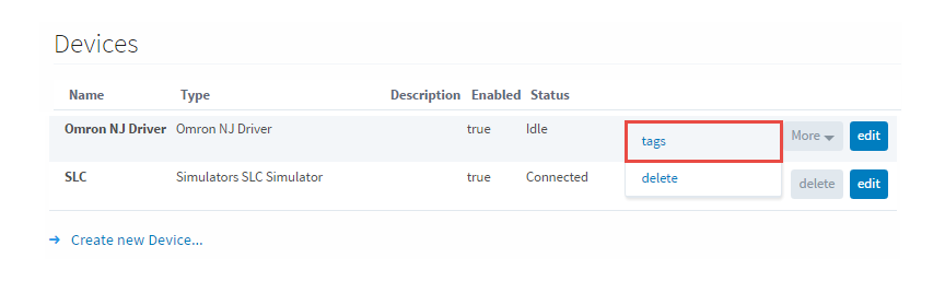
- On the Devices page, click the Tags link next to the newly created device. The Manage Tags page is displayed, allowing you to configure which variables in the device will show up as Tags in Ignition.
Device Settings
General Settings
| Name | Description |
|---|---|
| Name | The user-defined name for this Device. The name chosen will show up in OPC Item Paths and under OPC-UA Server > Devices of the Configure page of the Gateway. The Device Name must be alphanumeric. |
| Description | The user-defined description for the device. This is only used as a note to differentiate between devices. |
| Enable Device | Only devices that are enabled appear in Connections > Devices of the Status page of the Gateway and thus have their tags available for use. |
Main Settings
| Name | Description |
|---|---|
| Hostname | The hostname or IP address of the device. |
| Timeout | The request timeout, specified in milliseconds. The default is 2,000. |
Advanced Settings
| Name | Description |
|---|---|
| Connection Size | The CIP connection size to use. The default (and maximum) is 1,994 bytes. |
| Slot Number | The slot number in the backplane in which the CPU is located. |
Exporting from the Device
To export variables from Sysmac Studio, navigate to the global variables and select Tools > Export Global Variables > CX-Designer.
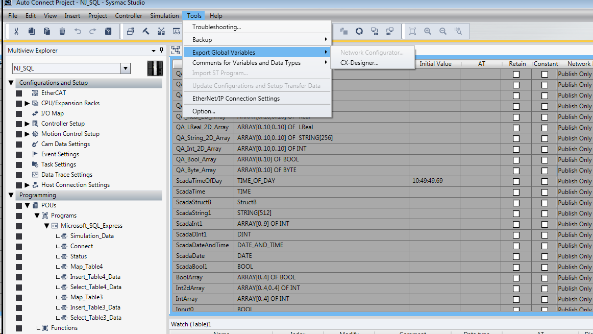
The variables will be saved to the clipboard in tab-separated format. You can now paste the contents into an empty text file for use with importing into the Ignition Gateway.
Managing Tags
In order to browse Tags in the Designer, you must first create a mapping for the device in the Gateway. The Manage Tags page can be accessed by navigating to the Omron device and clicking the Tags link.
Importing Tags
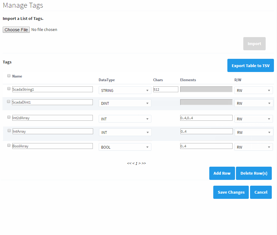
Once on the Manage Tags page, you can manually enter the Tags, or import them from a tab-separated file. When importing, first choose a file, then click the Import button. The default option when importing is to replace the Tags table with Tags from the import. Select the append option to append Tags to the table.

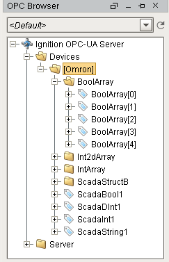
Once you save any changes made to the Tag mapping, you can view the Tags in the Designer OPC Browser.
Addressing
In the Tags table of the Manage Tags page, we have four columns of configuration per Tag:
- Name - The corresponding address of the variable found in the Omron device. Struct members are separated with periods.
- Datatype - The datatype of the variable found in the Omron device.
- Chars - The maximum number of characters that a String Tag will contain.
- Elements - Denotes whether the Tag is considered a scalar or array. See below for more detail on specifying the number of elements to read from the device.
- R/W - Specifies read / write access permissions on the Tag.
Scalars
Leaving the Elements column blank will result in a scalar Tag. When reading from the device, only one element will be requested.
![]()
Arrays
Specify the number of elements in an array in the form of 0..N. The initial index 0 is always included, so an array mapped with 0..4 elements is a 5 element array.
![]()
The number range specified in the Elements field can deviate from the range specified in the device's program. Thus, if an array was configured with a range of 0 - 4, but the mapping on the Ignition Gateway is set to 3 - 7, then the resulting items would be offset as follows:
| PLC Program | Tag in Ignition |
|---|---|
| 0 | BoolArray_3_ |
| 1 | BoolArray_4_ |
| 2 | BoolArray_5_ |
| 3 | BoolArray_6_ |
| 4 | BoolArray_7_ |
This is because the driver always assumes that the lowest configured element on the mapping page matches up with the lowest element in the PLC program. As seen above, this can cause some confusion if the mapping on the Ignition Gateway is configured with a different range.
For this reason, it is highly recommended to configure the Elements field on the Ignition Gateway to match the range used in the PLC program.
Note, that this also applies to Multidimensional Arrays.
Multidimensional Arrays
Multidimensional arrays are specified in the same way as arrays with each group of indices separated by a comma.
![]()
Array elements may also be specified with a single number equaling the total number of elements.
![]()
Strings The number of characters for String variables is specified in the Chars field.
![]()
String arrays are mapped using both the Chars and Elements fields.
![]()