Gateway Network Diagram
Gateway Network Diagram Overview
The Gateway Network Diagram is a visual representation of your Gateway Network. You can access the Live Diagram tab by going to your Gateway webpage's Status tab > Connections > Gateway Network > Live Diagram.

If your 8.1 Gateway is connected to a 7.9 legacy Gateway, a banner will be displayed at the top of both the Gateway Network and Gateway Live Diagram pages, which warns that your 7.9 Gateway will not be able to communicate with your current Gateway, should it be upgraded from 8.1 to 8.3.
Gateway Network Diagram User Interface
To navigate the Diagram, you can use your mouse's left-click to pan around and your mouse's scroll wheel to zoom in or out. Additionally, you can drag and rearrange different nodes as you like. There are also different buttons on the Diagram interface that may be helpful:

| Icon | Element | Description |
|---|---|---|
| Filter box | Filters by Gateway name. You can use comma-delimited Gateway names so that multiple Gateways show through the filter. | |
| Download Live Diagram JSON | New in 8.1.38 Downloads the Gateway Network Diagram as a JSON file. | |
| Take screen capture | Takes a screenshot of the currently displayed Gateway Network Diagram. | |
| Use dagre layout | Displays the Gateway Network Diagram in a dagre, or top-down layout from the Perspective of the local Gateway. | |
| Use circular layout | Displays the Gateway Network Diagram in a circular layout, with the center being the local Gateway. | |
| Zoom in | Zooms into the Gateway Network Diagram. | |
| Zoom out | Zooms out of the Gateway Network Diagram. | |
| Reset zoom and center | Resets the camera panning and zoom and centers the Gateway Network Diagram. | |
| Open in new tab | Opens the Gateway Network Diagram in a new, separate tab. | |
| Refresh chart | Refreshes the Gateway Network Diagram so that the most recent Gateway Network configuration is shown. |
Gateway Network Diagram Details
Live Diagram Icons
The following table shows each Gateway Network Diagram icon and its description.
| Icon | Description |
|---|---|
| The local node from which you are viewing the Gateway Network Diagram. This icon's orange color also indicates that the node is running Standard Edition. | |
| The Gateway node that the local Gateway is connected to. This icon's orange color also indicates that the connected node is running Standard Edition. | |
| The local node from which you are viewing the Gateway Network Diagram. This icon's green color also indicates that the node is running Edge Edition. | |
| The Gateway node that the local Gateway is connected to. This icon's green color also indicates that the connected node is running Edge Edition. | |
| The local node from which you are viewing the Gateway Network Diagram. The icon's multicolor also indicates that the node is running Maker Edition. | |
| The Gateway node that the local Gateway is connected to. The icon's multicolor also indicates that the connected node is running Maker Edition. | |
| The local node from which you are viewing the Gateway Network Diagram. The icon's blue color also indicates that the node is running Cloud Edition. | |
| The Gateway node that the local Gateway is connected to. The icon's blue color also indicates that the connected node is running Cloud Edition. |
Connection Details
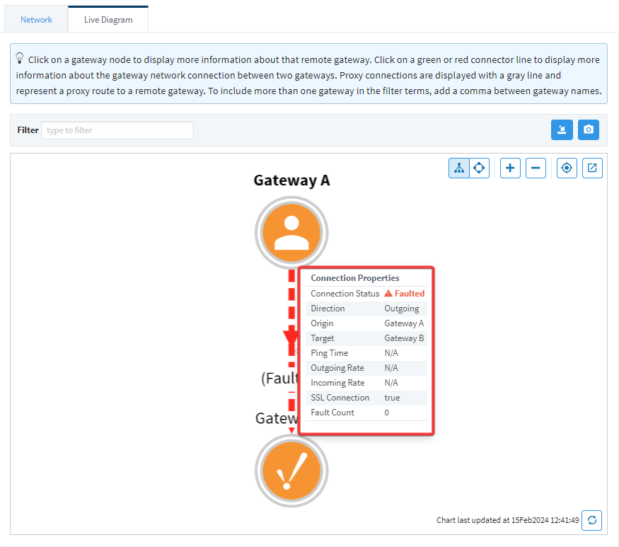
You can find out more information about each node and connection by clicking on them in the diagram. For example, clicking on the connection itself will display information such as:
- Connection Status
- Direction (Outgoing versus Incoming)
- Origin Gateway and Target Gateway
- Ping time in milliseconds
- Rates (Outgoing and Incoming bytes per second)
- Whether the connection is using SSL
- How many times the connection has faulted

If the connection is in another state besides Running, the Diagram will update accordingly:
Gateway Nodes
On the other hand, clicking on the Gateway node itself will display information such as:
- Gateway Name
- Network Address
- Version
- Edition
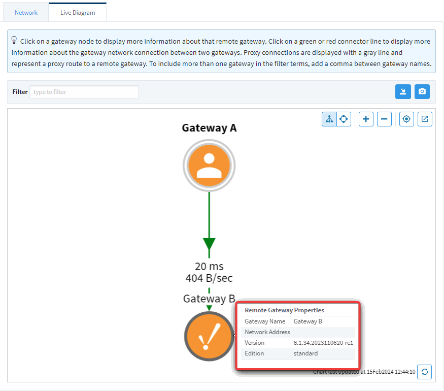
If a Gateway in your Gateway Network is running Ignition version 8.1.24 or below, the Version and Edition fields will be N/A.
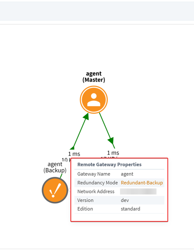
Redundancy Representation
If two Gateways are part of a redundant pair, the diagram will show each Gateway node with an orange circle around it. In addition to the Gateway Name, Network Address, Version, and Edition, the Gateway Node will also display the Gateway's role in the redundant pair:
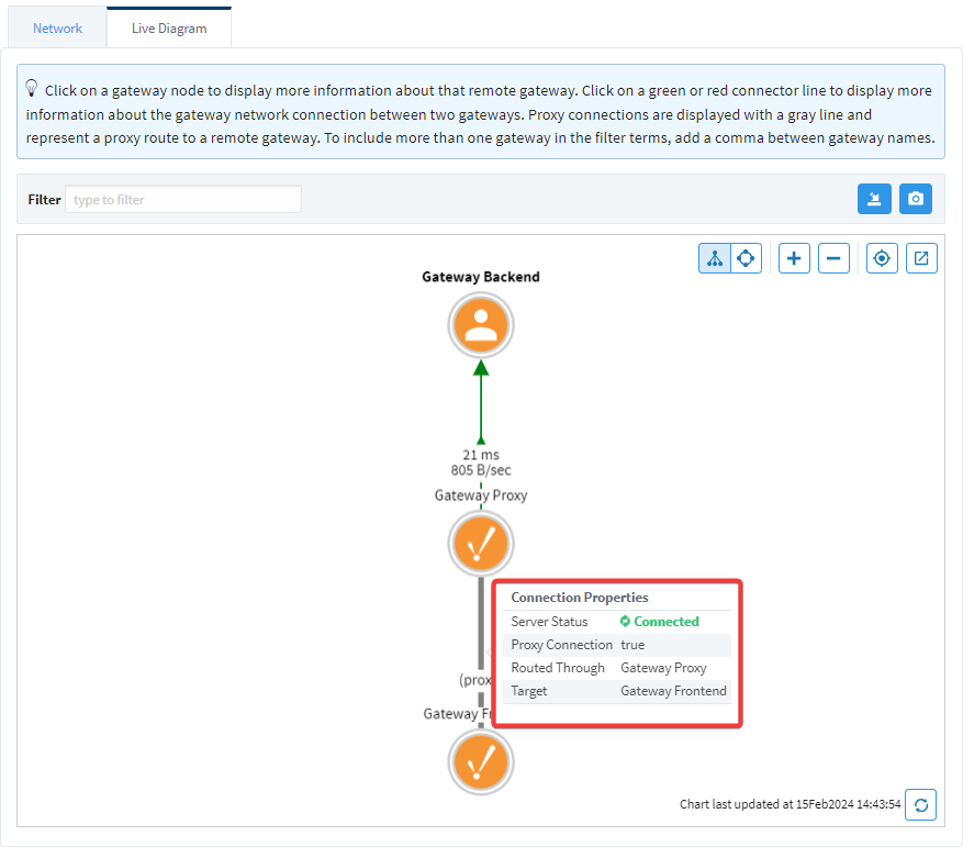
Proxy Connections
The Gateway Network Diagram will also display proxy connections differently. Instead of a green arrow indicating status and direction, the connection will be grey with no direction indicator. Clicking on a proxy connection will give the following information:
- The status of the server
- Whether or not the two Gateways are using a Proxy connection
- Which Gateway the proxy is routed through
- The proxy connection's target Gateway