Designing a Project
This document follows the Downloading and Installing Ignition guide from the previous section and assumes you have enabled the Quick Start feature on the Gateway. See the Commissioning the Gateway section for more details.
Additionally, this guide will use the Perspective module to visualize our data and project. The resources configured within the Gateway's Quick Start, including the Device Simulator, tags, Tag Historian, and Internal Alarm Journal, will also be used for this project.
The project this guide creates will start from a blank Perspective project and end with several components with bindings that interact, as well as visualizing historical tag data, and creating an alarming system that alerts users if a tag reaches a certain threshold. By the end of this guide, we will have a simple project that looks similar to this:

Creating the Project
To begin working on a project, we will first need to create one.
-
In the Designer Launcher, select the Gateway to create the project on and then click Open.... We will be using our locally installed Gateway in this guide.
-
The Designer will initialize and then prompt you for login credentials. Use the credentials you set up when first commissioning the Gateway.
-
After logging in, a list of projects on the Gateway will be displayed. Click on + New Project on the top left. This will bring you to the New Project Setup page.
noteSince we enabled Quick Start on the Gateway, we will already have a project titled Sample Quick Start. This project is a good example of what your own project can eventually look like, but for the purposes of this guide, we will create a new project.
-
Give your project a name and title, then click Create New Project. Your new project will initialize and open the Designer. We will call our project myProject and give it a title of My Project.
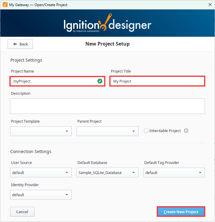
Your project should now be ready to build in.
Working in Perspective
This section will encompass all the steps taken within the Designer's Perspective workspace.
Creating a View
Since we are using Perspective, we will need to first create a view.
-
In the Project Browser on the top left of the Designer, expand the Perspective Module.
-
Right-click on the Views folder and select New View.... A New View configuration window will pop up.
-
Give your new view a name and choose a Root Container type, then click Create View. We will name our view myView and keep the default Coordinate Container selection.

Your view is now created and has a blank workspace to begin designing your project.
Preparing Perspective Components
Let's start putting components into our view. Components are the main features an operator interacts with within a project and includes things like charts, input components, and display components.
-
Begin by dragging two Cylindrical Tanks, a Slider, and a Progress Bar from the Perspective Component Palette onto your workspace and orient them on the bottom as shown in the image below. We will bind these together using tag data in a later section.
 tip
tipYou can use the Designer's red dotted guiding lines to help line up components so that they are on the same axis.
-
Next, drag an Alarm Journal Table to the space above the components from the previous step. We will use this table to display our alarm history in a later section.

-
Drag a Time Series Chart from the Component Palette onto the top of your workspace. Use the handles to resize the component so that it sits flush with the top of the view and the top of the Alarm Journal Table. We will use this to visualize your tag's historical data in a later section.

-
Save your project.
Your components are now ready to have tags bound to them to display data.
Adding Tags from a Device
Since components visualize and interact with data, they do not do anything if no tags or data is bound. This section will go over the most common way a component gets data to display, typically from PLCs or external devices through an OPC UA connection using OPC tags.
In this example, we will use the Gateway Quick Start's preconfigured Device Simulator, as this mimics an external device that tags pull data from. The steps below assume you already have a Device Simulator configured from Quick Start. See the Connecting with OPC UA section for details on creating a connection to a physical device or Device Simulator if you did not enable Quick Start.
-
Go to the Tag Browser on the bottom left of your Designer.

-
Click on the Add
 icon, then select Browse Devices. This will bring up the Connected Devices popup.
-
The Ignition OPC UA Server will populate under the OPC Browser column. Go to the Device Simulator by expanding Ignition OPC UA Server > Devices. The preconfigured simulator will be called [Sample_Device].

-
Expand the [Sample_Device] folder and click on the Random folder. This folder contains all the tags we need for this basic project.
noteYou can choose to import all the tags from your device. However, since we don't need the other tags on the Device Simulator, we will just import the Random folder.
-
With the Random folder selected, click on the Add
 icon in the middle of the Connected Devices popup. This will add the Random folder and its tags to the staging area for import.
 tip
tipYou can add tags to a different Tag Provider than the default provider by changing the provider in the Tag Browser before importing any tags.
-
Click OK to add the Random folder.
The folder and tags within will now appear in the Tag Browser.
Creating Tags Within the Tag Browser
Besides pulling tags from a device over OPC UA, you can also create your own tag. This section will demonstrate how to create a Memory tag, which will be used in a later section.
-
In the Tag Browser, click on the Add
icon, then select New Standard Tag > Memory Tag. This will open the Tag Editor.
-
Give your tag a name. We will name our tag myMemoryTag. Since we are making a simple binding to a component, we do not need to configure any other properties at this time. After you have named your tag, click OK.

Your Memory tag is now created and ready to use.
Setting Up Tag History
Now that your tags have been created, we can set up history on the tags we will be using. This lets us record historical tag values and display them to see trends and past data.
Storing historical data typically requires setting up a database connection and a history provider.
We will be storing history to the SQLite SQL Historian resource configured by the Gateway's Quick Start when first commissioning the Gateway.
Even though we are using the SQLite database connection for this example, it is NOT recommended to store history using SQLite. A dedicated external database, such as Microsoft SQL Server or MySQL, should be used instead, as they will handle the potential amount of writes and reads needed for development and production data much better.
-
In the Tag Browser, right-click on the Memory tag you created, then select Edit tag(s). This will open the Tag Editor.
-
Click on the History category of the Categories section.

-
Under the History Enabled property, change the field from false to true. This will enable the rest of the history fields.
-
Under the Storage Provider property, change the field to the history provider you set up previously. In this example, we will be using the Sample_SQLite_Database configured from Quick Start.
-
Click OK to save these settings.
We will now do the same thing with the tag in the Random folder that we will be binding later.
-
In the Tag Browser, expand the Random folder, right-click on RandomInteger1, and then select Edit tag(s). This will open the Tag Editor.
-
Click on the History category of the Categories section.
-
Under the History Enabled property, change the field from false to true. This will enable the rest of the history fields.
-
Under the Storage Provider property, change the field to the history provider you set up previously. In this example, we will be using the Sample_SQLite_Database configured from Quick Start.
-
Click OK to save these settings.
Binding Tags to Components
Now that we have added our Perspective components, configured our tags, and enabled history on them, we can start binding them to our Perspective components to visualize our data.
Binding the Memory Tag
We'll first bind our Memory tag to the Slider and left Cylindrical Tank. This will allow us to control our Memory tag using our Slider and easily see the tag's value through the Cylindrical Tank.
-
In the Perspective Workspace, click on the Slider component. Selecting the Slider will populate the Perspective Property Editor with the Slider's configurable settings.
tipYou can also select the Slider in the Project Browser by navigating through Perspective > Views > myView > root > Slider. Other components are also selectable through the Project Browser.
-
Go to the value property. You'll notice that hovering over this property will cause a light gray Add Binding
 icon to appear. Click on the icon to open the Edit Binding window.
 -
Click on the Tag Binding Type. This will open the Configure Tag Binding section.

-
Click on the Browse Tags
 icon to the right of the Tag Path field. This will open a navigatable tree.
 -
Within the tree, expand the Tags folder and select the Memory tag you created previously, then click OK. This will populate the Tag Path field with your Memory tag.
 note
noteIf you do not have a value for your Memory tag by the end of the Slider Tag binding process, the Tag binding will still work, but an error will be shown.
-
Toggle the Bidirectional property to enable it. This will allow our Slider to control our Memory tag.
-
Click OK.
You'll notice that changing the Slider will now also update your Memory tag. Next, we'll bind the Cylindrical Tank to display the Memory tag's value.
-
Click on the left Cylindrical Tank.
-
Click on the Add Binding
icon for the Cylindrical Tank's value property. -
In the Edit Binding window, click on the Tag Binding Type.
-
Click on the Browse Tags
icon. -
Expand the Tags folder, select your Memory tag, then click OK.
noteWe did not enable the Bidirectional property for the Cylindrical Tank. This is because we are only using the Cylindrical Tank to read the tag's value without writing to it.
Your Cylindrical Tank should now be displaying your Memory tag's value. To test your binding, set the Designer to Preview Mode and enable both read and write functionality. Notice that when adjusting the Slider, the Cylindrical Tank's value will also adjust.
Binding the OPC Tag
Now we'll bind our OPC tag RandomInteger1 to our Progress Bar and right Cylindrical Tank. This will allow users to see the values coming in from our RandomInteger1 tag.
-
In the Perspective Workspace, click on the Progress Bar component. Selecting the Progress Bar will populate the Perspective Property Editor with the Progress Bar's configurable settings.
-
Go to the value property and click on the Add Binding
icon. This will open the Edit Binding window. -
Select the Tag Binding Type. This will open the Configure Tag Binding section.
-
Click on the Browse Tags
icon to the right of the Tag Path field. -
In the tag tree, navigate to Tags > Random, select RandomInteger1, and press OK.

-
Click OK on the Edit Binding window. Note that we don't have to enable the Bidirectional option since the Progress Bar will only read the tag value and not write.
Your Progress Bar is now displaying your RandomInteger1 tag value. We'll now do the same for our second Cylindrical Tank.
-
Click on the right Cylindrical Tank.
-
Click on the Add Binding
icon for the Cylindrical Tank's value property. -
In the Edit Binding window, click on the Tag Binding Type.
-
Click on the Browse Tags
icon. -
In the tag tree, navigate to Tags > Random, select RandomInteger1, and press OK.
-
Click OK on the Edit Binding window. Similar to the Progress Bar, we don't have to enable the Bidirectional option since the Cylindrical Tank will only read the tag value and not write.
Your second Cylindrical Tank should now be displaying the same value as your Progress Bar.
Displaying Tag History
Now that we have our tags' live values displayed in our project, let's focus on displaying our tags' history. To do this, we will bind our historical data to the Time Series Chart we created in the Preparing Perspective Components section.
-
Click on The Time Series Chart to bring up its properties in the Perspective Property Editor. The property we will want to utilize is series.
-
Expand the series property, and then the 0 property if they aren't expanded already. You'll notice that unlike the previous component properties, there are additional subproperties beneath series. This is because unlike value, series is an array that contains multiple sources of data.
-
Click on the Add Binding
icon for the Chart's series > 0 > data property. -
Select the Tag History Binding Type.
-
Change the Time Range property to Historical.

-
Click on the Browse Tags
icon. -
In the tag tree, navigate to Historical Providers > Sample_SQLite_Database > myGateway:default. Select your Memory tag, and then press OK.

-
Press OK on the Edit Binding window.
Your Memory tag's history should now be displayed on the Time Series Chart. We'll now add the historical data from RandomInteger1.
-
Click on The Time Series Chart to bring up its properties in the Perspective Property Editor.
-
Since series is an array, we can add additional properties to it. Hovering over the series property will bring up an Add Array Element...
 icon. Click on this icon to add an element to the array. This will add a new 1 property under series.
-
Click on the Add Binding
icon for the Chart's series > 1 > data property. -
Select the Tag History Binding Type.
-
Change the Time Range property to Historical.
-
Click on the Browse Tags
icon. -
In the tag tree, navigate to Historical Providers > Sample_SQLite_Database > myGateway:default > random. Select RandomInteger1, and then press OK.

-
Press OK on the Edit Binding window.
Your RandomInteger1 OPC tag should now also be displayed on the Time Series Chart.
Configuring Alarms
Another common task is to set up alarms on your tags. This section will demonstrate how to navigate through the various Gateway and Designer sections set up an alarm on a tag and notify a user.
Setting up an alarm and corresponding notifications consists of three parts: an On-Call Roster, a Notification Profile, and an Alarm Notification Pipeline. The On-Call Roster determines who receives notifcations, while the Notification Profile determines how they are delivered. Then, the Alarm Notification Pipeline incorporates both of these to control alarm notifications for designated tag alarms.
Creating an On-Call Roster
We'll first set up an On-Call Roster on the Gateway. If your Gateway is installed locally, you can access your Gateway at http://localhost:8088/.
-
Navigate to Services > Alarming > Rosters.

-
Click on Create Alarm Roster +.
-
Give your roster a name, then click Create Alarm Roster. We will name ours myRoster.
-
Click on the three dots menu on the right of the new roster, and click Manage Users.

-
Select default from the Select User Source dropdown. The default User Source contains the admin user you created when first commissioning the Gateway.
-
With the admin user displayed, click on the Add to Roster
 icon and then Save Changes on the bottom right.
Your admin user is now part of the roster.
Creating an Alarm Notification Profile
Next, we'll set up an Email Notification Profile for our Notification Profile. All Notification Profile options and their settings are described on the Notification Profile Types page.
-
Navigate to Services > Alarming > Notification.
-
Click on Create Profile +.
-
Select the Email Notification option. Click Next.
-
Fill in the required fields. Take note of the Username field, as you will need this value later. Once you have filled out the form, click Create Alarm Notification Profile. In this example, we used the following values:
- Name: Email Profile
- Hostname: mail@inductiveautomation.com
- Username: user@inductiveautomation.com
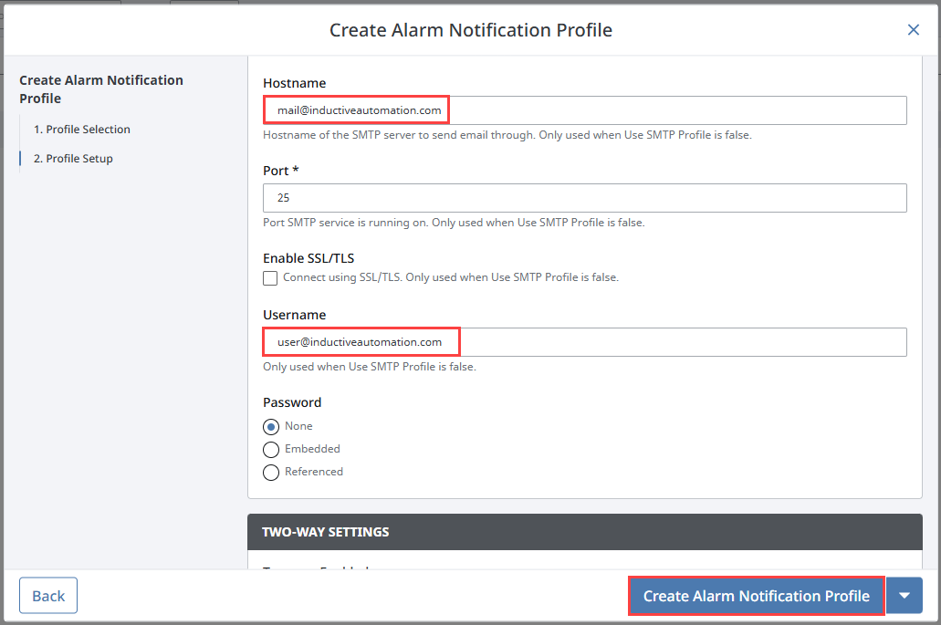
Your Email Notification Profile has been created and now needs contact information to be set up before it is ready to use.
Adding Contact Information
The Email Notification Profile requires matching contact information to be added to our On-Call Roster user in order to send out alarm alerts.
-
Navgiate to Platform > Security > User Sources.
-
Click on the three dots menu on the default user source, and select Manage Users.

-
Click on the three dots menu on the admin user, and select Edit.

-
Under the Contact section, click Add + to add a new row.
-
Change the Type to E-Mail, and enter the Email Notification Profile Username in the Value field.
-
Click the Save
 icon, then click Save Changes.
Your admin user is now ready to begin receiving alarm notifications.
Creating an Alarm Pipeline
Now, we'll access the Designer to set up an alarm pipeline and configure how and when alarm notifications are sent out.
-
In the Project Browser, right-click on Alarm Notification Pipelines and then select New Alarm Pipeline. We will name our pipeline myPipeline.
-
Drag a Notification block from the top bar down to the Alarm Pipeline workspace.
-
Click on the Notification block to display the Notification Block properties in the Pipeline Block Editor.

-
In the Notification tab, click on the dropdown menu and select your Notification Profile. Ours is called Email Profile.
-
Click on the Contacts tab and select the On-Call Roster we created. Ours is called myRoster.
-
On the Alarm Pipeline workspace, connect the START node to the IN node of your Notification block, then save your project.
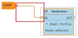
Now that we've created an Alarm Notification Pipeline, we can use it on the tags we want to keep an eye on. In this example, we'll configure an alarm on the RandomInteger1 tag that's available from the Gateway's Quick Start resources.
-
In the Tag Browser, expand the Random folder, right-click on RandomInteger1, and then select Edit tag(s). If your Tag Browser isn't currently displayed, navigate back to the view you created in your Perspective project. The Designer interface will change and show the Tag Browser again.
-
Select the Alarms category, then click the Add
 icon.
icon. -
Under Alarm Mode Settings, change the Mode to Above Setpoint and the Setpoint to 85. This will cause the alarm to trip if the tag value reaches 85 or above.
-
Under Notification > Active Pipeline, select the pipeline we created and then click OK.
Your alarm will now send an email notification to the admin user's contact information whenever the RandomInteger1 tag value exceeds setpoint. You can test this out by changing the tag's value, and even add an Alarm Journal Table component to a view to display alarm history. This component works with the Gateway's Alarm Journal from Quick Start.
Displaying Alarm History
We'll now utilize the Alarm Journal component we put on our project in step 2 of Preparing Perspective Components.
-
Go to your Alarm Journal Table component.
-
Change the name property to the actual name of the Alarm Journal configured in your Gateway. If you are using the Quick Start, the name should be
Sample_Alarm_Journal_Profile.
Your Alarm Journal Table will now populate with the data from the Gateway's Alarm Journal. Further details on the Gateway Alarming settings can be found in the Alarm Notification section, while more information about alarm states, schedules, and usage with tags can be found in the Alarming section.
Accessing Your Project
Now that you have finished your project, you can launch the application to see what it looks like to an operator. You can view your project through the Designer's Preview Mode, launch the application through the Designer's Tools Menu, or use Perspective Workstation.
View Your Project in Preview Mode
Preview Mode will allow you to interact with your project as if you were an operator without needing to leave the Designer.
-
Click on the Project menu item at the top of the Designer.
-
Toggle Preview Mode to enable it.
View Your Project Through the Tools Menu
Using the Designer's Tools Menu will allow you to launch your project without using a launcher.
-
Click on the Tools menu item at the top of the Designer.
-
Navigate to the Launch Perspective... option, then click Launch Session.
View Your Project Using Perspective Workstation
Perspective Workstation is usually how operators would launch your Perspective project. Because of this, it is recommended to ensure your project launches correctly through the Perspective Workstation launcher.
-
Open the Perspective Workstation launcher we installed in the Downloading and Installing Ignition section.
-
Click Add... on the bottom of the launcher.

-
Select the local Gateway, then click Select Gateway.

-
Select the project we just created, then click Add Application(s). Your project will be added to the My Applications window.

-
Click on your project, then click Open....

Perspective Workstation will launch your project and you can now interact with it as if you were an operator.